State Machine Diagram
Contents
Rationale and Underlying Metamodel
The OMG UML 2.5.1 specification, 14.1 states:
The StateMachines package defines a set of concepts that can be used for modeling discrete event-driven Behaviors using a finite state-machine formalism. In addition to expressing the Behavior of parts of a system ...
From the UML 2.5.1 specification, 14.2.3:
a StateMachine instance may execute a potentially complex sequence of Behaviors associated with the particular elements of the graphs that are being traversed (transition effects, state entry and state exit Behaviors, etc.)
Due to its event-driven nature, a StateMachine execution is either in transit or in state, alternating between the two. It is in transit when an event is dispatched that matches at least one of its associated Triggers. While in transit, it may execute a number of Behaviors associated with the paths it is taking.
NOTE. A StateMachine execution may be executing Behaviors even when it has settled in a stable state configuration, in cases where there are doActivity Behaviors associated with its active state configuration.‘OMG Unified Modeling Language (OMG UML™). Version 2.5.1’, The Object Management Group, formal/2017-12-05, Dec. 2017. https://www.omg.org/spec/UML/2.5.1/PDF.
TRAK Resource elements (Job, Organisation, Physical, Role, Software and System) may have behaviour and hence may be related to a State:-
- Resource exhibits State
Potential triggers include behaviour (Function), Events and the exchange between 2 Resources (Resource Interaction):-
- Event triggers State
- Function triggers State
- Resource Interaction triggers State
- State triggers Event
- State triggers Function
- State triggers Resource Interaction
Note that there is a consistency check required if a State triggers a Function which then causes an Event then the same State must trigger the same Event. Similarly in the reverse direction.

Elements and Connectors (Triples) - Linking a State Machine Diagram with TRAK
In the TRAK metamodel Contract, Requirement and Standard may govern any Architecture Description Element hence also State and similarly in the reverse compliance or conformance direction using 'satisfies'. A Claim or Concern may be raised about any element and similarly an Argument in an assurance case may be linked to any element.

Elements and Connectors (Triples) - Linking State Machine Diagram with TRAK Universal Elements
Example State Machine Diagram
The following dummy State Machine Diagram was prepared using Sparx Systems Enterprise Architect.

A UML State Machine Diagram Annotated with TRAK Elements - Argument, Claim, Concern, Requirement, Resource (Job), Standard
Features
Bare Profile
The bare UML profiles provide a set of node and connector elements which allow the triples shown on the metamodel diagram above to be created.
UML
The UML-TRAK profile (this project) provides UseCase, applies to, defines collaborator as, extend, include, refines, specializes which inherit properties from the TRAK Architecture Description Element provided by the (TRAK) profile.
The TRAK (UML) profile from trakumlprofile provides Resource elements (Job, Organisation, Physical, Role, Software and System).
The TRAK (UML) profile also provides elements to create universal triples that may appear on any architecture view - Argument, Claim, Concern, Contract, Document, Standard, 'about', 'governs', 'satisfies' and 'traces to'.
SysML
The SYSML-TRAK profile (this project) extends the TRAK_SYSML profile from trakumlprofile providing Resource elements (Job, Organisation, Physical, Role, Software and System) as SysML Block elements.
The SYSML-TRAK profile (this project) extends the TRAK-UML profile (this project) and provides UseCase, applies to, defines collaborator as, extend, include, refines, specializes.
MDG (Sparx Systems Enterprise Architect)
The MDG for Sparx EA uses the bare UML and SysML profiles and also other Sparx EA-only profiles that provide functionality and modify the user interface within Sparx EA.
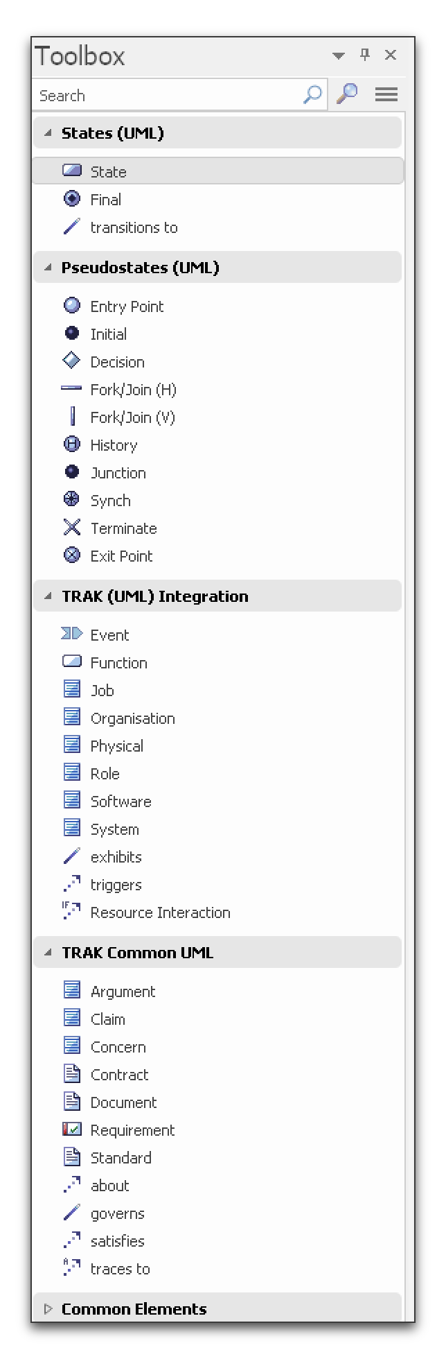
Custom Toolbox Provides the Elements to Create UML State Machine Diagram
The MDG for Sparx EA when loaded provides:-
- customised toolbox palette adding
- States - State and Final Entry Point, Initial, Decision, Fork/Join, History, Junction, Synch, Terminate, Exit Point and transitions to
- TRAK Integration - Event, Function, Job, Organisation, Physical, Role, System and Software
- TRAK Common Elements - Claim, Concern, Contract, Document, Requirement, Standard, about, governs, traces to
- Repository - All States
- Quality - Resources not exhibiting any State
- Quality - States not exhibited by any Resource
- hiding of guillemets (« ») on node and connector element labels (where EA allows!)
- display of State and 'transitions to' identifier in label based on 'id' property value
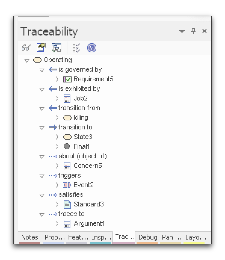
Custom Traceability Panel Labels (Sparx Enterprise Architect) - Operating State Selected
Note that simply placing a State inside another State creates an invisible 'owns' relationship which isn't otherwise visible - hence the 'owned by' in the reverse direction. This is standard behaviour of the UML and the SysML.
Other References
See also the TRAK SV-11 Solution Event Causes architecture view used to describe the causes of Events and their impacts on Resources and Functions.
The UML / SysML with TRAK is subject to the terms of open source license: (CC BY-SA 4.0) Creative Commons Attribution-ShareAlike 4.0 International license (version 4 ) at https://creativecommons.org/licenses/by-sa/4.0/.